% man mf
One needs the program mf and some Metafont input file. On an Ubuntu system mf is part of the texlive-binaries package, probably installed already. Part of the TeX distribution (in the texlive-base package) is the example file io.mf. You probably already have it. (Or just find a random .mf file somewhere.)
% mf io.mf
(/usr/share/texmf-texlive/metafont/base/io.mf
The letter O [79])
*
An enormous window appears, either completely empty or with a single O in the upper left hand corner. The window cannot be closed or deleted. Type 'end' at the prompt to quit mf.
*end
Output written on io.2602gf (1 character, 1724 bytes).
That worked, but is rather inconvenient. The 'end' was needed because mf, after reading its input files, continues reading from the terminal, until it sees an end command, and there was no end in io.mf. Since my own .mf font files do end in end, that is not a problem. Still, running mf on a font file will throw up a window, I have to place it, and immediately afterwards it is closed again when mf finishes. This silly behaviour can be suppressed by running mf-nowin. One has to tell mf-nowin to fake the name mf, otherwise one gets error messages about a missing mf-nowin.base. And to redirect stderr, since mf-nowin likes to clutter the screen by telling you that there is also a version that throws up nice big windows. Yes, we know. Put the resulting command in a little file runmf.
% cat runmf
#!/bin/sh
mf-nowin -progname=mf "$1" < /dev/null 2> /dev/null
% chmod +x runmf
% ./runmf io.mf
Output written on io.2602gf (1 character, 1724 bytes).
%
(See the Metafontbook for examples of how to play with io.mf.)
mode_setup;

% parameters are name, width, height over base line, depth below base line
beginchar ("a", 9pt#, 12pt#, 0);
  alpha:=0.65;
  beta:=0.24;

  % define points
  x1 = 0; y1 = 0.8*h;
  x4 = w; y4 = 0.2*h;
  y2 = h; y3 = 0;
  x2 = (alpha-beta)*w;
  x5 = alpha*w;
  x3 = (alpha+beta)*w;
  y5 = 0.5*h;
  x6 = 0; y6 = 0.3*h;
  x7 = 0.2*w; y7 = 0;
  x8 = x5; y8 = 0.2*h;

  % define pen
  pickup pencircle xscaled 0.2w yscaled 0.04w rotated 30;

  % draw
  draw z1{dir 30}..z2{right}..z5{down}..z3{right}..z4{dir 30};
  draw z5..z6{down}..z7{right}..z8;
  penlabels(1,2,3,4,5,6,7,8);
endchar;

end
It starts with mode_setup; to initialize various things,
and ends with end. Every command ends in a semicolon,
except for the final end. Comments start with %.
A character description starts with beginchar(...) and ends with endchar;. The parameters of beginchar(...) are the name of the character (a font index, here 97, the ASCII code of "a"), the width, the height above, and the depth below the base line. Inside the character description these three values are available as w, h, and d.
Let us first run the example, and look at the result.
% ./runmf a.mf
Output written on a.2602gf (1 character, 2960 bytes).
% gftodvi a.2602gf
% xdvi a.dvi
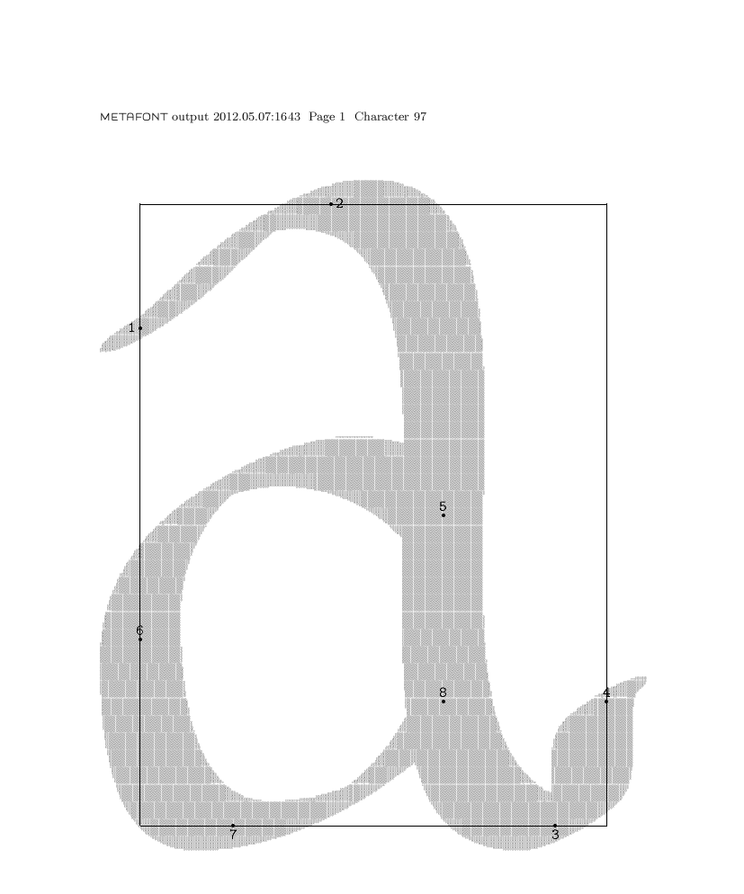
This example defined eight points and drew two strokes. The command penlabels(1,2,3,4,5,6,7,8); caused dots to be drawn at these point positions.
The two draw lines draw the two strokes. One passing through the points 1, 2, 5, 3, 4 and the other through 5, 6, 7, 8. Metafont will draw nice curves passing through the indicated points, but one can give additional restrictions on the curves. Here the {down} for points 5 and 6 means that the curve should be vertical at those points. The {right} that it should be horizontal at points 2, 3, 7. The {dir 30} that it should slope upwards under an angle of 30 degrees at points 1 and 4.
The strokes are drawn using a pen that was defined in the pickup line: a circle scaled in the x-direction to width 0.2w, and in the y-direction to height 0.04w (so that one gets a wide, flat ellipse) and then turned counterclockwise by 30 degrees.
The points have names like z5, where z5 has coordinates (x5,y5). One can specify coordinates explicitly, as done here, but also as a system of equations, saying for example x3-x5 = x5-x2.
The * can be omitted in expressions like 0.2*h. Equals signs = indicate a system of equations to be solved. Colon-equals := is an assignment.
So far about this example.
% cat runtest
#!/bin/sh
rm -f $1.600pk
mf "\mode=localfont; mag=4; input $1"
(echo "$1"; echo '\\sample'; echo '\\bye') | tex testfont
xdvi testfont.dvi
% chmod +x runtest
% ./runtest xyzzy
The rm here removes the previous version of xyzzy.600pk so that this file will be regenerated. The script shows that one can give a (quoted) command line to mf.
\documentclass[a4paper]{article}
\newfont{\foo}{xyzzy}

\begin{document}

{\foo Hello world!}

\end{document}
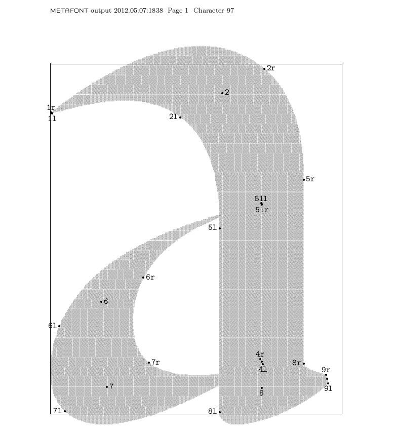
The above example used a suitably shaped pen to draw curves. One can also use an entirely different method and define outlines to be filled. The picture here was produced by
mode_setup;

% parameters are name, width, height over base line, depth below base line
beginchar ("a", 10pt#, 12pt#, 0);

  % placement vertical stem (left) and stem width
  shl := 2.25pt;
  sw := 3.33pt;

  % serif end angle and width and height above bottom and prev height
  sea := 105;
  sew := 0.025h;
  seb := 0.10h;
  sdy := 0.075h;

  % initial angles
  a := 30;
  ar := a+180-15;

  % hor shift
  w0 := w-1pt;
  x0 := 0.5pt;

  % define points
  x1 = x0-0.05w0; y1 = 0.86h;
  x2 = x0+0.6w0; y2=h-pt;
  x4 = x5 = x8 = x0+w0-shl;
  x9 = x0+w0;
  y5 = 0.6h; z51 = z5;
  x6 = x0+0.14w0; y6 = 0.32h;
  x7 = x0+0.16w0; y7 = 0.077h;
  y4 = 0.15h;
  y8 = sdy;
  y9 = seb;

  % define pen angles
  penpos1(0.05pt,120);
  penpos2(sw,30);
  penpos5(sw,30);
  penpos51(0.05pt,300);
  penpos6(sw,30);
  penpos7(sw,30);
  penpos4(0.2pt,120);
  penpos8(sw,30);
  penpos9(sew,sea);

  penstroke z51e{dir ar}..z6e..tension 1.1..z7e
    ..tension 1.3..{dir a}z4;
  penstroke z1e{curl 0}..z2e..{down}z5e..{down}z8e
    ..{down}z8e..tension 1.5..{curl 0}z9e;

  penlabels(1,2,4,5,51,6,7,8,9);
endchar;

end
This messy source defines some variables, then some points,
then some penpositions and finally draws two penstrokes.
The command penpos7(b,a) defines two new points
z7l and z7r in terms of the point z7 by
(i) z7 = 0.5[z7l,z7r] (that is, z7 is halfway
z7l and z7r), and
(ii) z7r-z7l = (b,0) rotated a
(that is, the distance between x7l and x7r
is b, and the direction from one to the other is a).
A penstroke using points like z7e draws a curve through the left endpoints and one through the right endpoints, and then fills the interior. The curves should not intersect, otherwise mf no longer knows what part is the interior and complains about a `strange curve'.
We had {dir a} directions before. Here also ..tension x.. (to pull the curve tighter) and {curl c} (to indicate initial curvature) are used.