Introduction
The indoor localization technique is based on infrared LEDs and sensors, which are operated similar to touch panels. When that technique is applied to an area with the size of a office room or shopping area, some additional problems occur:
- Due to doors, windows, furniture and walking corridors, it is not possible to construct the system as a single hardware unit. Therefore, it will be a distributed system.
- Due to the distances between LEDs and sensors, the received infrared signal might be very weak.
- The accuracy of the localization depends on the distances between consecutive LEDs, which is directly related to the costs of the installation. For the proper trade-off between costs and accuracy, the system should be very modular.
- During the installation of the system, the LEDs and sensors have to be callibrated, such that sensors are correctly aligned with the illumination patterns of the LEDs.
In a final product, the hardware could look similar to LED strips, such as those based on the WS2812B chip. However, those LED strips don't provide detection capabilities and the communication protocol doesn't allow the retrieval of information.
Hardware Configuration
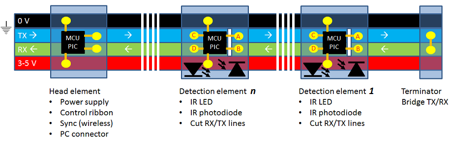 A possible hardware configuration is shown in the figure above, where the ribbon is a 4-wire flat cable, which provides the power (black and red) and communication (blue and green) lines.
Electronic elements can be clicked on the flat cable to create a functional detection segment. The following electronic elements are expected:
A possible hardware configuration is shown in the figure above, where the ribbon is a 4-wire flat cable, which provides the power (black and red) and communication (blue and green) lines.
Electronic elements can be clicked on the flat cable to create a functional detection segment. The following electronic elements are expected:
- A head element controls the activity of the other elements on the ribbon segment and provides the power to those elements. When a room contains multiple segments, the head element is also responsible for the synchronization and to report the IR sensor detections to the localization algorithm (for example through USB or wireless).
- A detection element contains an infrared LED and photodiode and its activity is based on the commands received over the communication line.
- A terminator element is used to indicate the end of the segment, which would usually be the end of the ribbon or flat cable. In principle, a single ribbon can contain multiple (consecutive) segments, if that improves the performance.
The communication between elements is done using the two communication lines. A detection element cuts these two lines, such that it can communication directly with its direct neighbors on the ribbon. The communication can be bitwise (digital I/O toggling) or bytewise (UART).
Note that it is possible to use a ribbon with additional lines, such as a clock controlled by the head element.
Software Configuration
The activation of LEDs within a segment and between segments needs to be synchronized to ensure that IR detections can be related to the correct IR emissions. Within a segment, the synchronization is based on the theory of systolic arrays. Each detection element executes the following communication pattern repeatedly:
    (C?x ; A!x)n-1 ;
     C?x ; start IR LED modulation or detection ; A!x ;
     C?x ; stop IR LED modulation or detection  ; D!y ;
    (B?y ; D!y)n-1
where n indicates the position of the element within the segment, which is also the identity of that element (unique within the segment).
The x values indicate the commands given to the detection elements, for example to perform a detection or to select a modulation scheme for the IR LED. The y values provide the results of the detection. The first line forwards the commands to the elements with a lower identity.
The second line starts modulation of the LED or the detection with the photodiode based on the received command.
The third line stops the modulation or the detection and returns the detection result.
The fourth line forwards the detection results from the elements with a lower identity.
When all elements operate at the same speed, the IR activation and detection will be synchronized. The synchronization between segments is based on a wireless clock synchronization protocol.
The communications on A and C between the start and stop of LED modulation (or IR detection) are used to control the duration of the LED modulation. By adjusting the speed of the communication protocol (for example, the baudrate of the UART), it is possible to control the duty cycle of the LED (which is the major factor in the energy consumption of the segment) and the cycle time for the segment and the system (that is, the total time required for activating all LEDs).
The position of the detection element within the segment is automatically determined with the following communication pattern for the initialization:
A!1 ; B?n ; C?x ; D!(n+1)
The communication on B retrieves the identity as assigned by the neighbor towards the remainder of the segment, while the communication on D assigns the identity to the neighbor towards the head of the segment. Due to the communication on A and the terminator element that connects A directly to B, the last detection element of a segment will assign the identity 1 to itself. The communication on C is used for synchronization (to ensure that the element is started), but the received value is ignored.
The head element of a segment controls the behaviour of the detection elements by sending the correct control commands to the detection element that is directly connected. For a segment of length N, the head element will send N commands for the individual detection elements, followed by one command to stop the LED modulation or IR detection. After the commands are send, the head element will receive N detection results. In total, it will take 2*N+1 communications to perform one detection. In theory, the head element can send new commands while the detection results are received (reducing the value to N+1), but it depends on the selected hardware whether the synchronization can still be guaranteed. In case of serial line communication, the baudrate of the UART would determine the performance of the system.
To properly cover the detection area within a room, it is likely that multiple segments have to be installed, where each segment can have a different number of detection elements. In that case, the synchronization between IR LED activations and detections becomes a bit more complicated. One possible solution is to send dummy commands which are ignored by detection elements, such that each segment has the same communication pattern. In that case the performance of the system is determined by the maximum length of a segment. It is possible to reduce the length of a segment by attaching extra terminator and head elements to a ribbon, although that would introduce additional communication and synchronization between all head elements.
Testbed Implementation
To verify that the described hardware and software configuration will work, the prototype of the system is constructed. In the prototype, the following hardware elements are used:
- The selected MCU is an MSP430 F1611, as used on BSN nodes from ICL, which we previously used within the WASP project. These sensor nodes are similar to TelosB nodes, although they have a smaller form factor and a suitable extension board. The MSP430 microcontroller provides two UART interfaces, several A/D convertors for the IR photodiode and general I/O pins to control the IR LED. The BSN platform contains a CC2420 chip for wireless communication (IEEE 802.15.4) and provides USB connectivity, which is useful for the head elements.
- The selected IR LED is a Vishay VSMB10940, which is a compact LED with an wide angle emission.
- The selected IR photodiode is a Vishay BPW41N, which has a wide angle of sensitivity and a large radiant sensitive area.
The prototype does not use a flat cable and clickable electronic elements. Instead, the hardware is placed in an off-the-shelf plastic casing. Below are some photos of the hardware configuration:
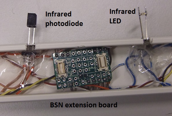
One detection unit, consisting of a BSN node, an IR photodiode and IR LED.
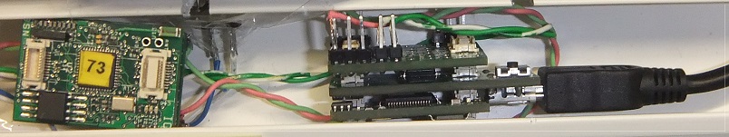
One detection element (labeled 73) and a head element connected to USB.
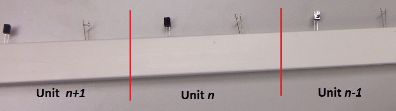
A bar with three detection units.
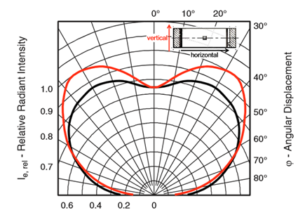
The wide emission angle of the IR LED is required for the horizontal coverage of the room, in particular the IR photodiodes at the opposite side of the room. However, the selected IR LED has a circular emission pattern (similar to most LEDs), as indicated by the figure below (from the hardware specification).
In order to increase the detection range of the system, the vertical emission pattern is focussed into a narrow beam with a cylindrical lens, as shown in the following figure.
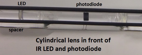
The lens reduces the emission area and increases the radiant intensity. For the photodiode, the lens focusses the incoming infrared light onto the radiant sensitive area. The characteristics of the lens are not optimized for this particular application and a customized lens might further improve the performance and the detection range. With the proper lens, it is possible to create a very narrow beam of IR light. However, with a narrow beam, the installation and callibration of the system becomes more complex due to the allignment of LED emissions and IR photodiodes.
a
To reduce the interference of external infrared light sources, the lens and the photodiode are surrounded by black material, such the IR reflections are blocked. In a final product, such an IR blocker could have any color, as long as it blocks/absorbs the relevant IR frequency.
The software for the MSP430 is developed on top of a locally developed operating system. The communication between detection elements is based on serial line (UART) communication. The described application is implemented in the related interrupt service routines (ISRs), such that the system is only driven by the communication behavior. In particular, there are no timer-activated tasks, such that timer ISR can be disabled and doesn't interfere with the synchronization.
For the testbed, two segments are constructed, each with nine detection elements. The distances between the IR LEDs and photodiodes is six centimeter. The head element can either connect to USB or communicate wirelessly using IEEE 802.15.4.
Energy consumption.
Detection ranges.
Detection cycle time.
The current system activates a single IR LED at a time, which is detected by the photodiodes. When the hardware platform provides support for FFT operations, multiple IR LEDs could modulate the IR emission with different frequencies, such that the FFT of the A/D measurements can be used to detect multiple frequencies. In that case, the detection cycle time can be improved.